|
[HUMAN-POWERED FLIGHT BY AN AMATEUR FEMAL PILOT]
3. Human-Powered Aircraft for Female
Design and manufacturing of HYPER-CHick "KoToNoLimited'' One of unique advantages of Japanese women is the light weight and small body. In this project, the body of the pilot is very compact, 154cm tall and 44Kg in weight. She has experienced the broad jump in a usual high school and made a woman's record of flight distance of 157.4m which is the second place in the successive glider class of the JIBR. Moreover she has been dreaming to extend her record in the broad jump. Therefore she was said to be the most suitable girl for a pilot of HPF. 3.1 Possibility of Flight by an Amateur Female Pilot. It is said that force, power and endurance of the muscles of a female are from 20 to 30 % smaller than those of a male. Moreover, the rate of improvement by training is also 50% lower. However, female have the one advantage of light weight. It is well known that a saving of 1Kg mass is equivalent to 3 watts power saving in HPF. As her weight is only 44Kg, required power for flight is 63 watts less than that of the average man. In this case, required power to keep straight level flight is estimated to be only 164 watts. Assuming that combined efficiency of power transmission and propeller is 75%, then 220 watts pedaling power is required for level flight. During take off and climbing, it becomes 30% more, up to
At the time of begining of training, we assured her basic muscle power showed 220 watts for 60 seconds. From that data, we believed firmly that she could continue to fly for the duration within the limits of her anaerobics power.
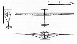
3.2 Design of the Aircraft The design concept of the aircraft is to allow her to be able to take off and climb with her own super small power. The gross weight is 80Kg and the lift per drag ratio is larger than 30. We investigated thoroughly the construction to achieve the lowest wing loading and span loading (load per unit length of wing). As a result, pipes made from Carbon Fiber Reinforced Plastics(CFRP) was decided to be applied for the main frame to make it simple and rigid. 3.2.1 Wing The construction weight becomes heavier as the wing aspect ratio becomes higher. The main dimensions of the wing are decided according to the optimization study of the relation between weight and aspect ratio. The total length of the main spar is 25.8m. The diameters of the main spar at the tip and root are 47.5mm and 95.5mm respectively. The wall thickness is gradually changed from 0.75mm to 1.5mm by 0.25mm steps. It is increased from the tip to the position where a lift wire is connected. After then, it is decreased and increased again up to the root of wing. 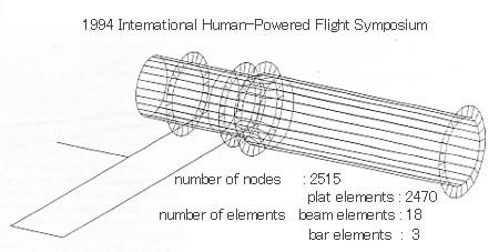 Fig4. FEM analysis model Rigidity of a pipe with thin wall is decreased due to oval deformation of the cross section from original circle to ellipse under bending moment. To avoid it, the pipes are reinforced by installing ribs on it using adhesives. Wing ribs are made from expanded poltstyrene board and ring plates from balsa plywood adhere on both sides around the holes. To examine the effect of the reinforcement, deformation and stress on the pipes are analyzed using Finite Element Method (xFEM). And the calculated results for both cases, with and without the ring plates, are compared. The pipe is divided into 24 elements along the circumference, and into 58 elements along the longitudinal direction. Each element is assumed a plate. Reinforcement rings are also divided into 24 elements which are perpendicular to the elements of pipe. The calculation results show that wing tip deflection of the reinforced spar is smaller than that of the original spar. And it shows that the shape of the cross section of the original pipe deforms to the ellipse. The deformation ratio is slightly smaller near the position where the lift wire is attached. On the other hand, it is apparently decreased all over the total length when the ring plates are attached. It seems that the rings restrict the deformation of the cross section and avoid decreases of rigidity, and then decrease the deflection of the wing. 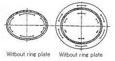 Fig5. Stress distribution of the section 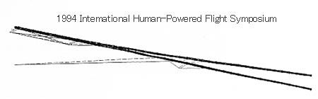 Fig6. Deflection of the spar After then, stress distribution on the cross section is compared in both cases. The difference is very small near the position where the lift wire is connected, whether the ribs have ring plates or not. But stress dsceases up to 30% on the other position when the ribs have ring plates. It is several percent at the top and bottom, and it is from 10% to 30% at the leading and trailing edge sides. Compression stress appears on the upper part, tension stress appears on the bottom half of the pipe cross section in both cases. On the contrary, tension stress on the upper part and compression stress on lower part of the ring plates themselves appear when the spar is reinforced with it. That is, the stress of the opposite direction appears on the cross section of the spar and the ring plates. From the calculation, it is understood that ring plates restrict the deformation of the cross section of spar as well as joints of bamboo and hoops of barrel. The effect seems not only to avoid the unstable bending but also to keep the bending rigidity. We could finally achieve the minimum weight within allowable deflection by the combination of five kinds of tapered CFRP pipes of which thickness is changed by 3 to 4 steps. Deflection and weight were decreased 6% and 2.5%, respectively, comparing those of conventional spar. The airfoil "DAE-11" is applied to the whole span of the wing. It is designed by MIT for the HPA "Daedalus". It is intended to design better profile from the view point not only of aerodynamics performance but also of easiness of manufacturing. We could easily make smooth leading edge and sharp trailing edge precisely and moreover avoid the deformation of the airfoil by the heat shrinking of the covering film. 3.2.2. Fuselage Before manufacturing, we investigated the best configuration using mockup of cockpit. Finally we selected the reclining style of cockpits as both arms of the pilot can be always free, the light weight and low center of gravity are possible, and the power transmission system becomes simple. The construction of the main frame has a comparatively large safety factor in order to endure the severe load which is anticipated to occur at the bigining of training flight by an amateur pilot. To avoid the fracture at the connection of each main pipe, it is reinforced with pipes of the length of from 7 to 8 times of pipe diameter in order to disperse transmitted force and stress, to shorten the buckling length of the pipe and to increase the in-plane stiffness. But unfortunately, it increases the weight contrary. The chain drive system is selected for driving a propeller from the view point of easy handling. The special acceleration system is also equipped to get rapid acceleration, shorten take-off ground run, and fit the pilot's acceleration capacity. It consists of two wheels on main gear and pedal axis. Kevlar rope which is wound on the rear wheel is wound up to the front wheel during acceleration. Various kinds of forces act on the cockpit frame, which are tension of the chain, empty weight, the pilot's weight and reaction force for pedaling. Those loads are not only static but dynamic force. It is known that the tensile strength of CFRP composite material is degraded after a large compression stress is loaded. This is caused by uneven distribution of forces on each carbon fiber filament after the failure of the matrix which is combined with fiber. This results in progressive failure. It seems that the fracture does not caused by only high Young's modulus and small failure strain. Therefore we paid attention to the parts on which a large cyclic and impact force are loaded. Front pipes of the cockpit on which the nose gear pedals, driving chain and maneuvering lever are connected are made from hybrid material composed of carbon and glass fibers. It is anticipated that the pipe becomes tough like a yield of steel because the fracture begins on the carbon fiber of which the elongation rate is small and ends on the glass fiber. 3.2.3 Tail Drag and weight of tail wings are reduced by introducing flying tail system. It is found that the wooden structure has enough bending and torsional stiffness and the lightest in case of this size. The spar was composed by tapered spruse flange and balsa wood web. 3.3 Manufacturing and Schedule Control The period of the project was very short, about only 10 months. The project started in September 1991 and we have to carry the aircraft to the Lake Biwa in order to attend the JIBR on 1st August next year. Therefore we decided to challenge the official record flight in the first week on June and July. To keep the rapid schedule it was very important to control the man-hours. The network chart by the arrow type is established according to our efficiency data accumulated from manufacturing experience of three kinds of wooden gliding aircrafts for past the JIBR. The designing was started in September 1991, and the manufacturing in Octorber. Almost half of the required parts were finished manufacturing in the end of the year. The assembly was started in January 1992. The test flight was scheduled on April. There were many critical pathes on the diagram and we did not have any float. We used CFRP material for main frames for the first time. In order to keep the good quality, we gained the pipes from the factory which was guaranteed the quality. All of the other parts were made by our hands. Only the completed parts were carried into the Yoshikawa's(3) house to control the assembly schedule. As we has not any special manufacturing shop, the wings were assembled in a living room successively and stocked in a narrow cabin made under the eaves, and the cockpit was assembled in a garage running a risk of a violation of parking. We checked the schedule once every two weeks. The first priority was man-power-schedule. When we were behind in the schedule, we sometimes tried to catch it by doing the several works simultaneously if possible, or changing the order of works. For the result of those efforts, we could shorten man-hour from 2300(MH) to 2057.6(MH), keeping high quality. 
 |
|||||||||||||||||||||||||||||||||||||||||||||||||||||||||||||||